Posts

Showing posts from May, 2017

Problem countered during competition.

Image
During the competition, what we expected was wrong.  The robot is not working as we planned because the sensor become very sensitive and not follow as our plan. and the voltage supply cannot supply as a requirement for the circuit. As can be seen in the video below, the robot move slow and doesn't follow the track correctly. Part 1 Part 2 Part 3 Part 4

Line Follower Robot Competition

Image
For the competition day, first we have to calibrate the code to work properly with the hardware that we gonna built. So the first step in programming is to studying our circuit track for the competition. This will help our testing code and simulation. There will be two track which is for preliminary round and final round.  For the preliminary round we will compete about 38 teams before eligible to final round which is only 10 team will be selected. Preliminary Round Final Round Maze Circuit for Final Round Challenges to be faced by the participants during the Final Round when their robot will face the maze circuit. For this track, our lecturer have told us  and give some advice which is to add more sensor to our robot  possible turns and bends.  When it comes to programming a line follower robot it doesn’t mean you can just copy paste a bunch of code from somewhere and say you are done programming but we needs to prepare according wi...

The robot almost complete after many test procedure done..

Image
We testing the circuit for black and white response from sensor. testing video.. after testing was done, we move the circuit to the robot..

WORKING PROCEDURE

Image
TROUBLESHOOT SOLDERING BUILD THE ROBOT TESTING THE FINAL ROBOT WITH BLACK TAPE After we done the simulation by using software Keil's uvision and Proteus, we proceed by using hardware. All components and materials that we have been bought we will use to trouble the project. First things first we construct the circuit on the breadboard and check the connection between the IC to sensor, driver and dc motor by referring the circuit we have construct. We used battery 9 V to supply the circuit and also for our final robot.  Testing on breadboard Soldering some components Drilling holes for castor wheels Attaching the sensors Circuit for testing purpose

Testing code in simulation.

Image
After coding is done, we  test the code in the simulation. The code is shown in the previous post. As can be seen, the simulation works fine as we planned.

Circuit construction by simulation

Image
After we confirm all the components that we will used, we proceed to circuit construct by using software ISIS Proteus. 

Code for Robot

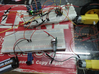
Based on the code below, we decided to use 5 IR sensor as input and 2 motor as output. The code for "PWM_test.c" has been shown in previous post. the function of PWM_test.c is to control the speed of the motor in this assignment. PWM_test.c produced rectangle signal to Port 1.0. The code of main body has been shown below. -------------------------------------------- CODE FOR MAIN BODY -------------------------------------------- #include <reg52.h>       /* Use reg52.h for header file */ #include "PWM_test.c"     /* Call the PWM_test.c in same folder*/ sbit s1=P2^1;        /* Declare sensor 1,2,3,4 & 5 to port 2*/ sbit s2=P2^2; sbit s3=P2^3; sbit s4=P2^4; sbit s5=P2^5; sbit R_motor1 = P3^3;     /* Declare motor driver 1 & 2 for forward and reverse function to port 3*/ sbit F_motor1 = P3^4; sbit R_motor2 = P3^0; sbit F_motor2 = P3^1; void main ()     /* main body*/ {  P3=0x00; ...

Header code

In this project, we use 2 header:         #include <reg52.h>         #include "PWM_test.c" For Reg52.h, we use it as a default without edit or customize any code. we also use Reg52.h because we choose AT89S52 as our microchip and we dont want any trouble when we create a code and make the robot working. For PWM_test.c, we use to control the speed and setup for the operation for DC motor. the code will shown below. ------------------------------------------------------PWM_test.c----------------------------------------------------- /* Global variables and definition */ /* Generates Timer interrupt Timer 0 at Osc Freq of 11.0592 MHz Note: PWM width 255~166 Max time delay is 65.536 ms*/ #include <reg52.h> unsigned char pwm_width; bit pwm_flag = 0; sbit PWM = P1^0; void pwm_setup(unsigned char Pulse) { TMOD = 0; //pwm_width = 160; pwm_width = Pulse; EA = 1; ET0 = 1; TR0 = 1; } ...