Posts

Assignment for task 1 (Buzzer)

Image
For this task, we need to build a buzzer. The game buzzer are widely used in school, colleges and tv programs. The team which presses the buzzer earlier is entitled to give the answer.  this buzzer works when as soon as any role pressed the pin, the buzzer will sound and the 7 segment show the player number. If other try to push the pin, there will be no output until the clear or stop button pushed. The assignment can be view on the video below.  Part 1 Demonstration Part 2 Demonstration Part 3 Demonstration The buzzer will sound for 200ms. For this buzzer, it wall sound a bit because the buzzer is small. Video for simulation: Schematic:  Flow Chart:  Block Diagram: ----------------------------------------------- CODE FOR BUZZER ---------------------------------------------- #include <reg51.h>     /*header file*/ unsigned int digi_val[6]={0x3F,0x86,0x5B,0x4F,0x66,0x6D};   /*unsigned int
Complete Robot after fixed the error.

Image
After troubleshooting done and some of faulty error has been fixed. We finally met with our goal. all the effort gave us the good result for our robot assignment, thanks also to our lecturers for their recommendations and solutions. Finally, the robot is  working fine as we planned and can move according to the black tape without any problem. Problem fixed. 1. Sensor     We change the sensor from 3 sensor to 5 sensor because 3 sensor is not enough for the robot to            detect the curve or junction of the tape. 2. PWM code.     We also adjust the speed of the motor so that the sensor can detect and measure the tape correctly. 3. Robot's body.     We also made some modification to the robot's body so that the robot will move smoothly. 

Problem countered during competition.

Image
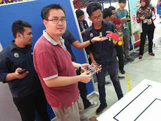
During the competition, what we expected was wrong.  The robot is not working as we planned because the sensor become very sensitive and not follow as our plan. and the voltage supply cannot supply as a requirement for the circuit. As can be seen in the video below, the robot move slow and doesn't follow the track correctly. Part 1 Part 2 Part 3 Part 4

Line Follower Robot Competition

Image
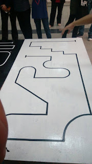
For the competition day, first we have to calibrate the code to work properly with the hardware that we gonna built. So the first step in programming is to studying our circuit track for the competition. This will help our testing code and simulation. There will be two track which is for preliminary round and final round.  For the preliminary round we will compete about 38 teams before eligible to final round which is only 10 team will be selected. Preliminary Round Final Round Maze Circuit for Final Round Challenges to be faced by the participants during the Final Round when their robot will face the maze circuit. For this track, our lecturer have told us  and give some advice which is to add more sensor to our robot  possible turns and bends.  When it comes to programming a line follower robot it doesn’t mean you can just copy paste a bunch of code from somewhere and say you are done programming but we needs to prepare according with the track given.

The robot almost complete after many test procedure done..

Image
We testing the circuit for black and white response from sensor. testing video.. after testing was done, we move the circuit to the robot..

WORKING PROCEDURE

Image
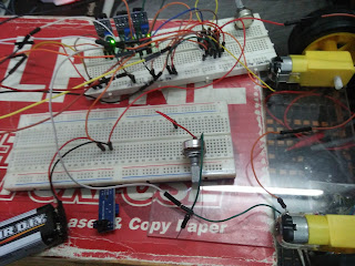
TROUBLESHOOT SOLDERING BUILD THE ROBOT TESTING THE FINAL ROBOT WITH BLACK TAPE After we done the simulation by using software Keil's uvision and Proteus, we proceed by using hardware. All components and materials that we have been bought we will use to trouble the project. First things first we construct the circuit on the breadboard and check the connection between the IC to sensor, driver and dc motor by referring the circuit we have construct. We used battery 9 V to supply the circuit and also for our final robot.  Testing on breadboard Soldering some components Drilling holes for castor wheels Attaching the sensors Circuit for testing purpose

Testing code in simulation.

Image
After coding is done, we  test the code in the simulation. The code is shown in the previous post. As can be seen, the simulation works fine as we planned.